Wenzhou Boshine Electronic Security Co. Ltd 
الصفحة الرئيسية> مدونة> Three-wire system for public broadcasting system wiring system

Three-wire system for public broadcasting system wiring system

July 26, 2022
The concept of the three-wire system The three-wire system is a wiring system in the public address system. It is suitable for the occasion where the broadcast terminal has a field volume controller, and it is necessary to forcibly insert an emergency broadcast in an emergency.

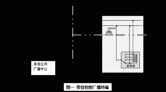
In the public address system, it is often necessary to configure a field volume controller for some broadcast terminals, such as the office of a supermarket, or a hotel room, so that the user can adjust the volume according to his or her needs, or completely turn off the broadcast of the terminal. A typical configuration is shown in Figure 1.


In Figure 1, the terminal with the live sound controller is off. Obviously, any emergency broadcasts cannot be inserted at this time. In fact, even if the sound controller is not fully closed and is in a low volume state, it is not conducive to issuing an alarm. In order to implement the emergency broadcast intrusion function, an in-line relay must be introduced. The most intuitive way is shown in Figure 2. It can be seen from Figure 2 that there are 4 pipe wells and ceiling wiring, and 5 wires for each terminal. In a relatively large system, the labor and materials are considerable. If you use a three-wire system, the benefits will be much better.

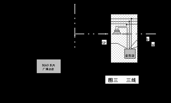
Figure 3 shows a typical three-wire system. The system consists of three lines from the broadcast control center (computer room) to the terminal. Correspondingly, both the sound controller and the broadcast power amplifier should be compatible with the three-wire system. The former is like the DSP/W series sound controller; the latter is the DSP/MAG series amplifier.


The principle of the second and third line system


The principle of the three-wire system is shown in Figure 4. The key to Figure 4 is the ring connection R. In the normal state, the R line is connected to the cold end (common end) of the amplifier output, and its circuit is the same as the simplest voice control terminal. During the strong insertion, the R line is switched to the hot end of the power amplifier output, so that the voice coil is short-circuited and placed at the hot end, so no matter what gear position of the voice-control switch is connected to the hot end directly, the emergency broadcast signal will be all Add to the terminal speaker.

As can be seen from Figure 4, in order to optimize the effect of the looping during the strong insertion, the voice coil type sound controller should be used instead of the resistor attenuator type sound controller; in addition, the three-wire power amplifier should have a built-in power amplifier. (Driven by the force-in command).

When using a resistor-attenuating type of tone controller, the three-wire system is still effective because the R line can connect the head and the tail of the attenuator. At this time, when the sound controller is in the off (or maximum) position, the emergency broadcast signal will also be added to the terminal speaker; if the sound controller is in other gears, the attenuator becomes a series with little resistance. Resistance, emergency broadcast signals can also be added to the terminal speakers. Of course, the effect will be worse.

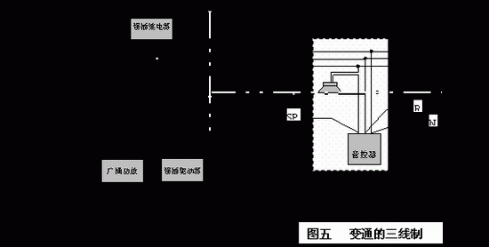
If a conventional power amplifier is used without a three-wire power amplifier, an in-line relay should be placed in the tube well and the corresponding drive components should be placed in the equipment room. Its configuration is shown in Figure 5. Among them, the broadcast power amplifier, the strong insertion driver, and the strong insertion relay can use the MP1500 series broadcast power amplifier, the MP9820 strong insertion driver and the WH-3 strong insertion relay of the DISP (DSP) respectively.


Third, easy to produce misunderstanding

As mentioned above, the R line in the three-wire system is a ring connection, but many people mistakenly think it is an emergency broadcast signal line. So they connected the system to Figure 6.


It is not difficult to see in conjunction with Figure 4 that this connection will result in severe crosstalk between background music broadcasts and emergency broadcasts, and this crosstalk will extend to the entire broadcast system connected to the system power amplifier.

In the three-wire system, background music and emergency broadcast signals (power signals) are transmitted by the same set of three lines. The switching of background music and emergency broadcast signals should be performed in the equipment room, and its configuration is shown in Figure 7. The switching commands come from the fire center or other systems that need to be forced. In the case of an intelligent system, signal switching is automatically implemented in the control center.


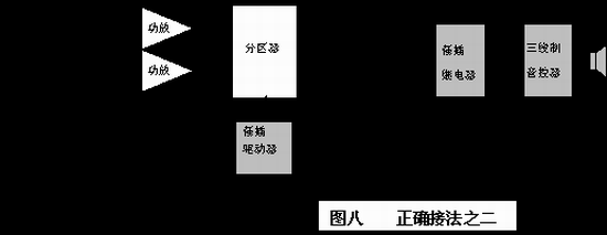
Another configuration is shown in Figure 8. This configuration can be used with conventional amplifiers such as the MP1500 series. The partitioner can be used with Disp (DSP)/MP9813. The partitioner has two power signal inputs that receive background music and emergency broadcast power signals respectively. The MP9813 has 10 channels of output for 10 public broadcast zones. Under the control of the switching command, only the partitions that need to be strongly inserted are switched to the emergency signal channel, while other partitions still release the background music broadcast.


The error in Figure 6 can also be corrected by using a four-wire tone controller, but there will be more than three wires, the details are omitted.


كونسنا

مؤلف:

Ms. CICI

بريد إلكتروني:

info@boshine.com

Phone/WhatsApp:

+8615058782622

المنتجات الشعبية
قد تعجبك أيضًا
الفئات ذات الصلة

البريد الإلكتروني لهذا المورد

الموضوع:
الالكتروني:
رسالة:

رسالتك MSS

كونسنا

مؤلف:

Ms. CICI

بريد إلكتروني:

info@boshine.com

Phone/WhatsApp:

+8615058782622

المنتجات الشعبية
  • ارسل السؤال
We will contact you immediately

Fill in more information so that we can get in touch with you faster

Privacy statement: Your privacy is very important to Us. Our company promises not to disclose your personal information to any external company with out your explicit permission.
إرسال